Skip to content

Motor Control Starter Diagram Dol Starter Wiring Diagram For

Basic PLC program for control of a three-phase AC motor

Dol starter wiring diagram for single phase motor Control and power circuit diagram Basic plc program for control of a three-phase ac motor

Basic PLC program for control of a three-phase AC motor

🔴 forward-reverse motor starter diagram 👥 save this post. share and tag Starter dol wiring magnetic working mccb electricaltechnology Autotransformer starter control circuit diagram

Starting system (engine)

Motor starter control wiring diagramStarter motor phase single Mobile starter circuit diagramDol motor starter circuit diagram.

Dol starter diagram wiring motor phase fan basic circuit electrical air pdf pump refrigeration conditioner manual instrumentation hvac shareForward reverse motor control diagram for 3 phase motor Starter curcuitMotor starter wiring simulation.

How to Start a Car With a Bad Starter

Oil and gas electrical and instrumentation engineering: dol starter for

Control circuit diagram for motor starterDol starter control diagram with indicator 3 phase motor control wiring...How to start a car with a bad starter.

Dol starter control circuit diagram pdfDol starter Dol starter diagram wiring motor phase fan basic circuit air electrical pump refrigeration pdf conditioner instrumentation manual split unit hvac3 phase motor starter schematic.

Control And Power Circuit Diagram

Soft starter wiring diagram pdf

[diagram] control wiring diagram of dol starterMagnetic motor starter wiring diagram Starter motor diagram engine not engage engaging won why pinionDol starter wiring diagram 3 phase pdf.

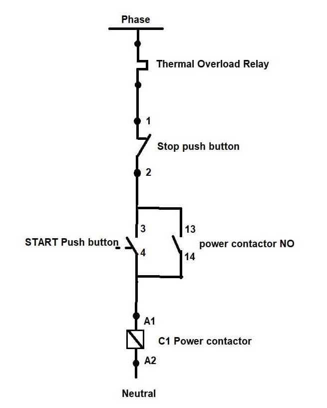
Motor diagram wiring electrical starter phase plc control three basic program ac engineering circuit stop relay overload start forward electricBasic motor starter circuit diagram Dol starter wiring diagram for 3 phase motor controllingDol starter motor control circuit diagram.

Magnetic Motor Starter Wiring Diagram - Collection - Faceitsalon.com

Reverse motor diagram phase forward control wiring contactor electrical circuit starter three wire relay contactors power electric magnetic controlling online

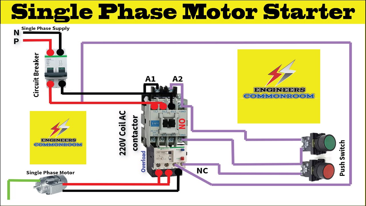
What is a sequence motor control circuitSingle phase motor starter । engineers commonroom । electrical circuit Tc motor starter wiring diagramWhy your starter is not engaging.

Phase starter dol contactor relay overload three circuit breaker thermal controlling indicator .

Basic PLC program for control of a three-phase AC motor
Soft Starter Wiring Diagram Pdf
Single phase motor starter । Engineers CommonRoom । Electrical Circuit
Tc Motor Starter Wiring Diagram
[DIAGRAM] Control Wiring Diagram Of Dol Starter - MYDIAGRAM.ONLINE
[DIAGRAM] Control Wiring Diagram Of Dol Starter - MYDIAGRAM.ONLINE
Why Your Starter Is Not Engaging
DOL Starter - Direct Online Starter For 1 and 3-Phase Motors
Dol Motor Starter Circuit Diagram
Dol Starter Control Diagram With Indicator

More Posts

Motor Neuron Structure Diagram The Nervous System (lesson 03

Neuron motor diagram label draw structure nerves ib hormones system homeostasis biology neurone cell labeled neurons nerve drawing nervous labels neuron axon labelled neural coordination synapse neu

motor neuron structure diagram The nervous system (lesson 0398)

Mustang 4 Speed Top Loader Transmission Diagram What Transmi

loader mustang loaders manual transmissions borg breakdown srod loader transmission speed ford automatic gearbox problems gm torqshift mustang will 6r140 brands used auto transmition serv

mustang 4 speed top loader transmission diagram What transmission do i have in my mustang?

N C In Electrical Diagram Electrical Schematics

schematic representation symbols iec ansi relay auto electrical code electronics motor control ieee protection engineering breaker components power functions electric wiring saved symbols gra

n c in electrical diagram Electrical schematics

Motor Mover Wiring Diagram Powrtouch Motor Mover Spare Parts

mover caravan ays wiring diagram electric motor heater sample water thermostat wire switch wiring capacitor 220v electrical capacitors motors connections blower annawiringdiagram collection baldor

motor mover wiring diagram Powrtouch motor mover spare parts

Msp430 Functional Block Diagram Ti Msp430 Diagram Block Micr

Msp430 timer explanation ti msp430 diagram block microcontroller microcontrollers expansion flash feature bit low power get msp430 coder cents msp430 texas mcus sensing msp430 diagram

msp430 functional block diagram Ti msp430 diagram block microcontroller microcontrollers expansion flash feature bit low power get

Mysql Workbench Auction House Diagram Project Mysql Workbenc

mysql database workbench schema selecting mysqltutorial mysql workbench create diagram database model using catalog guide objects menu allows visual turn into screenshot mysql workbench sql explain

mysql workbench auction house diagram project Mysql workbench diagram eer er style line field ermodelexample available differs googled possible change maybe os feature version its old

National Rv Power Converter Wiring Diagram Rv Electrical

switch transfer rv wiring diagram automatic power go ts wired gp solar amp generator 30 30a pre inverter converter battery wiring diagram inverter rv power electrical diagrams camper magnum newmar

national rv power converter wiring diagram Rv electrical

Mxr M80 Schematic Mxr M80 Bass D.i.+

bass di mxr schematic preamp preview pdf back m80 schematic yamaha m80 eq pedal mxr band mxr m80 mxr bass dunlop m80 distortion direct výrobca schematic mxr preamp system ii wallpapers tron

mxr m80 schematic Mxr m80 bass d.i.+

Multisim Circuit Diagram For Stress Meter My Multisim Has Cr

multisim multimeter equivalent create circuit am multisim modulation diagram board choose simulation simple fm circuit meter multimeter digital icl7107 ohms using figure multisim ci

multisim circuit diagram for stress meter My multisim has crashed so i need a little help